3. Structure of Programs with Deterministically Linked Modules
Modules are formatted program structures containing processed and control information. A set of modules linked by data, algorithmically and by sequential execution is called a module-linked program. Let a module-linked program P be given, where
Where PIj is the operational module of the program, or data, or input-output.
PIj= { UIj, ODj, LDj, Pj, SPPj, SPIj}
Where UIj is control information,
ODj is general data,
LDj is local data,
Pj is the processing program,
SPPj is the connection for searching for the module next in execution,
SPIj is the algorithmic connection of modules for transferring execution.
Data links (information links) define relationships between modules for moving common data values. Moving common data values is defined by place pointers in modules and movement moments. Moments show the start of moving values, and place pointers in modules show where common data values are moving from and where. Movement pointers and moments can be static and dynamic. Information links between program modules indicate the route of moving common data values across their used modules.
Module search links define the direction of their processing. They can be static and dynamic. Dynamic links are defined by conditions that depend on the properties of algorithms, data values, and the influence of data on algorithm execution. SPPj can be a program.
Search programs SPPj process the values of variables that determine the connectivity of modules for algorithmic processing. Module search links determine the connectivity of each module with subsequent modules. These links are used when searching for subsequent modules for their proactive movement between external and RAM devices.
Execution transfer link programs SPIj, which determine the algorithmic relationships of program modules, are specified either as static, or as an alternative depending on the order of module execution, or as a condition depending on data values. These links determine the input to the next module for processing.
Control information UIj determines the module type, local and common data areas, addresses of dynamic link programs SPPj and SPIj, constants of static links SPPj and SPIj. It also determines asynchronous, parallel, conflict-free access to the processing module, movement of common data values, analysis of links between modules, movement of modules in memory and input-output processes, according to their activity priorities.
The sequence of modules PI1…PIj…PIk, connected via search programs SPP1…SPPj…SPPk, is called a modular execution PPI of program P, if the sequence of processing programs P1…Pj…Pk determines the result of program P based on its data.
The execution of the processing program and the search program may depend on the values of the input modules, or they may be independent of them.
The information of the operational modules determines their processing, the movement of common data values between them. It is used to analyze the connectivity of modules, to search for them and move them around virtual memory.
Search programs, execution transfers, information links, and processing programs of different modules may have common data.
An important characteristic of a module-connected program is the structure of the links for searching for modules. Let the program P have a set {PPIl} of modular executions, where l=1…m.
Definition 7. The link structure for searching for modules of a program P is deterministic if, based on its data, it is possible to execute sequences {(SPP1…SPPj…SPPk)l} of module search programs for all modular executions {PPIl} of the program P.
Definition 8. A module-linked program P with a certain size of all modules is called a program with deterministically linked modules if the link structure for searching for its modules is deterministic.
In order to prove the possibility of constructing programs with deterministically linked modules for any class of equivalent algorithms, the formalism of operator schemes has been developed.
4. Operator Diagrams for Constructing Programs with Deterministically Linked Modules
The initial concept will be a graph. A graph in which the vertices represent operators, and the arcs represent possible transfers of control and data from one operator to another, forms the basis of operator diagrams.
Let program P be an enumerated list of elements {Оj} that have execution transfer links, as well as information links between their inputs and outputs, where each input has an information link from some output. For a sequential program, each element Оj is an operator, for a sequential-parallel program it is either an operator or a set of parallel operators, and for a parallel program it is a set of parallel operators. In what follows, for the sake of uniformity of terminology, element Оj will be considered a generalized operator (either an operator or a set of parallel operators), and operators will not be marked for now. When element Оj is a set of operators, it is assigned all the information links and execution transfer links of all operators in the set. Each chain of execution links corresponds to chains of information links.
The classes of sequential, sequential-parallel, and parallel programs intersect in the topology of links. Each operator has a certain number of arguments and results.
Operators have semantics {Wj,k}, according to which they transform arguments into results, where j=1,...,п; k=1,...,m.
Definition 9. A directed graph G(X,G,U), in which the operators of a program P are represented by nodes X = {O1, O2,…., On } of the graph, and the information links by data are specified by the function G: X<i></i> Y, and the links by execution between operators are specified by the function U: X<i></i> Y, is called an operator diagram of the program P.
Operator diagrams have input and output control nodes. Control is transferred to the operator diagram through input nodes. Output nodes terminate the control of the operator diagram.
A graphical representation of a program in the form of an operator diagram can be transferred to a representation of algorithms if its actions are represented by nodes of the graph.
Definition 10. An operator diagram is called connected by control transfer if the graph G (X, U) is connected.
We will consider the execution of an operator to be the act from starting the processing of arguments to transferring their execution after receiving the result. We will agree that the transfer of the result to other operators occurs simultaneously with the transfer of execution.
The order of execution of operators in the operator diagram is specified by the marking of information links, links for transferring execution and operators. Different types of operators have their own markings and links. For further presentation of the material, we will consider operator diagrams with a possible order of operator execution (without marking).
Definition 11. Operator
Oj is uniquely controlled by execution if it has one link for launching it for execution. Let us denote such a link for launching the operator for execution as
UZIj.. The link
UZIj.. is the input to the operator
Oj, The uniquely controlled operator will be depicted in the operator diagram as a circle with an incoming arrow:

O
Definition 12. Operator Oj uniquely controls execution if it has one link for transferring execution.
Let us denote such a link for transferring execution by the operator Oj as UPIj. The link UPIj. is the output from the operator Oj.
We will depict the unambiguously controlling operator in the operator diagram as a circle with an outgoing arrow:

O
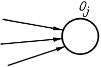
Definition 13. The operator Oj is alternatively controlled by execution if it has two or more connections for launching it for execution.
We will depict the alternatively controlled operator in the operator diagram as a circle with arrows entering it (
Figure 4):
Figure 4. Alternatively controlled operator.
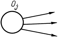
Definition 14. The operator Oj alternatively controls execution if it has several connections for the transfer of execution.
We will depict the alternative transfer of execution by the operator in the operator diagram as a circle with arrows coming out of it (
Figure 5):
Figure 5. Alternative transfer of execution by the operator.
Definition 15. An operator Oj is called polysemantic if it has different execution semantics.
Let us denote the execution semantics of a polysemantic operator Oj by {Wj,k}. Thus, we move from an interpreted scheme to a scheme over a class of interpretations.
Definition 16. The operator Oj is called polyinformational if it has several information links for transferring the result as operands (arguments) to other operators. We will depict a polyinformational operator in the operator diagram as a circle with double arrows coming out of it, the sources of information links will be marked with bold dots. Information links coming from one source merge into one bundle.
Definition 17. The operator diagram G(X,У,U) is called linear in execution if all operators in the diagram are uniquely controlled by execution and uniquely control execution.
A linear operator diagram graphically looks like this (
Figure 6):
Figure 6. Linear operator scheme.
Definition 18. An operator scheme G(X,Y,U), consisting of independent linear operator subschemes, is called a linear-type operator scheme in execution.
Each linear subscheme of a linear-type scheme has its own set of input data values. A linear-type operator scheme looks graphically as follows (
Figure 7):
Figure 7. Linear-like operator scheme in execution.
The operator through which control is transferred to the subcircuit will be called the input, and the operator through which the subcircuit transfers control will be called the output.
Definition 19. An operator subcircuit, that has one input operator through execution links, alternatively controlling two or more operators of the subcircuit, and one output operator from the subcircuit through execution links, alternatively controlled by two or more operators of the subcircuit, where the input and output operators are different, is called a hammock-shaped operator subcircuit in execution.
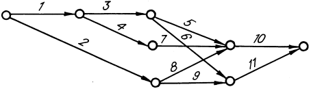
For example, the following operator subcircuit is hammock-shaped (
Figure 8):
Figure 8. Hammock-shaped operator subcircuit in execution.
In this hammock-shaped subcircuit, the alternatively controlled first operator О1 is the input operator to it through the execution links, and the alternatively controlled seventh operator О7 is the output operator from it through the execution links.
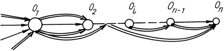
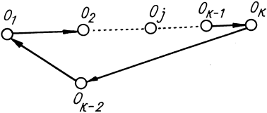
Definition 20. The operator subcircuit G((X0 <i></i> X), Г,U), in which the operators X0 ={Oj} form one closed chain (Oj1, Oj2,…,Ojn) through the execution links U:X0<i></i>X0, is called a non-linked operator subcircuit with return on execution.
The operator subcircuit with returns graphically looks like this (
Figure 9):
Figure 9. Operator subcircuit with returns.
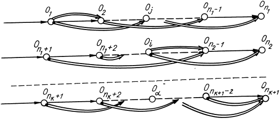
Definition 21. Operator subcircuits G((X1 <i></i> X), Y,U) and G((X2 <i></i> X),Г,U) with return on execution are called concatenated if the subcircuits have common operators X 1 <i></i> X2 = <i></i>.
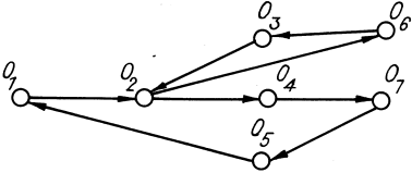
For example, the following operator circuit consists of concatenated subcircuits with returns (
Figure 10):
Figure 10. Linked subcircuits with returns.
Vertex O2 is a common vertex of linked subcircuits with returns.
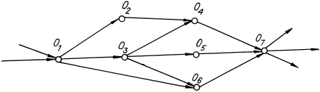
Definition 22. A nonlinear operator circuit G(X,G,U) without hammock-shaped subcircuits by execution and without subcircuits with return by execution is called a linearly cross operator circuit by execution.
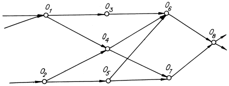
For example, the following operator subcircuit is linearly cross (
Figure 11):
Figure 11. Linear-cross operator subcircuit.
In the proposed formalism of operator schemes with natural interpretation, the following theorems are proved.
Theorem 1. In the operator scheme G(X,У, U), all hammock-shaped operator subschemes can be distinguished by execution.
Proof.
For each operator Oj0 of the operator scheme G(X,Y,U), we select all operator routes {(Oj0…Ojn)} via execution links. Consider all possible intersections of the selected routes. If the intersection of routes without the vertex Oj0 is not empty, then they form a hammock-shaped subcircuit of the scheme G(X,Y,U).
Which is what was to be proved.
Theorem 2. In the operator scheme G(X,Y,U), we can select all linked and non-linked operator subcircuits with return.
Proof.
In the operator scheme, for each vertex, routes with a repeating vertex are selected. These routes are operator subcircuits with return. Subcircuits with return on execution that have common vertices are linked.
Which is what was to be proved.
Theorem 3. In the linearly crossed operator scheme G(X,Y,U), all linear subschemes can be distinguished.
Proof.
In the original operator scheme G(X,Y,U), we distinguish operators {Oj(UZIj)}, operator schemes alternatively controlled by execution, and operators {Oj(UZIj)}, alternatively controlling the execution of the scheme operators, as follows.
For each operator Oj of the operator scheme G(X,Y,U), we calculate the functions U:Oj → X and U-1: Oj → X.. An operator Oj for which the set U-1(Oj) consists of more than one operator is an alternatively controlled by execution operator {Oj (UZIj), and an operator Oj for which the set U(Oj) consists of more than one operator is an alternatively controlling operator {Oj(UPIj)}..
In the operator circuit G(X,Y,U), we replace the operators {Oj (UZIj), alternatively controlled by execution and the operators {Oj (UPIj)} alternatively controlling execution with several unambiguously controlling and unambiguously controlled operators. We obtain subcircuits {G(Xi,Y,U)}, consisting only of unambiguously controlled and unambiguously controlling operators. Consequently, the subcircuits {G(Xi,Y,U)}, are linear operator subcircuits.
Which is what was to be proved.
4.1. Transformation of Operator Circuits by an Algorithmic Basis
We will consider the sequence of operators О1... Oi.... On of the operator circuit G(X,Y,U) to be its execution if each operator in the sequence is connected by control transfer and by information links only with subsequent (not necessarily adjacent) operators of the sequence.
Definition 23. The execution Oi1, Oi2,…, Oin of the operator circuit G1(X1,Y1,U1) and the execution Oj1,Oj2,…,Ojn of the operator circuit G2 (X2,Y2,U2) are called equivalent if for the same input data they lead to the same output data for natural interpretations of operator circuits as abstract programs and algorithms.
Definition 24. The operator circuits G1(X1,Y1,U1) and G2 (X2,Y2,U2) are called equivalent if the sets of their executions are equivalent.
Definition 25. The programs P1 and P2 that have equivalent operator circuits are called equivalent.
Definition 26. The transformation of the operator circuit of program P1 into the operator circuit of the equivalent program P2 is called the transformation of operator circuits by the algorithmic basis.
Let us introduce two rules of tolerant transformation of synthesis and splitting of operator schemes by basis.
Definition 27. Transformation of operator scheme G(X,Y,U), in which polysemantic polyinformation operator is obtained from subscheme G(X1,Y,U) of operator scheme G(X,Y,U) with preservation of all information links and links on transfer of execution with operator scheme G(X,Г,U), we will call synthesis.
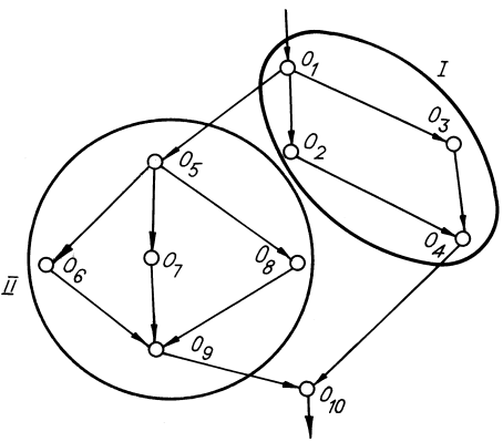
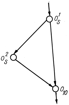
We will demonstrate synthesis of operator subscheme on the following example (
Figure 12):
Figure 12. Synthesis of an operator subcircuit.
The information links and operands of the synthesized operator Os are determined by the information links of the operators of the equivalent subcircuit with other operators of the circuit. The semantics of the operator Os is equivalent to the functional semantics of the equivalent subcircuit.
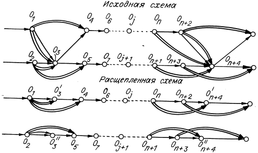
Definition 28. The transformation of an operator subcircuit into several independent subcircuits with the preservation of all information links and links for transferring control with the operator circuit is called splitting.
We will demonstrate the splitting of subcircuits of an operator circuit into independent ones using a simple example (
Figure 13):
Figure 13. Splitting of subcircuits of an operator circuit.
In the resulting subcircuits, only the necessary information links and operands remain, and only those links for the transfer of execution in these subcircuits that connect the operators of the subcircuits are preserved. Synthesis and splitting are the rules for transforming operator circuits according to the algorithmic basis.
4.2. Synthesis of Linear-cross Operator Circuits from Nonlinear Circuits
Theorem 4. An equivalent linearly cross operator scheme by execution can be synthesized from the operator scheme G(X,Y,U) with hammock-shaped operator subschemes by execution and with operator subschemes with returns by execution, linked and not linked.
Proof.
We synthesize polyinformation polysemantic operators {Oi} from each hammock-shaped operator subscheme G(Xi,Y,U).
We synthesize polyinformation polysemantic operators {Oi} from each linked and not linked operator subscheme G(Xj,Y,U).
In the original operator scheme G(X,Y,U), all hammock-shaped subschemas G(Xi,Y,U), concatenated and unconcatenated subschemas G(Xj,Y,U) with returns on execution are replaced by equivalent polysemantic polyinformational operators {Oi} and {Oj}.
We obtain an operator scheme G(X0,Y,U) without hammock-shaped subschemas and subschemas with returns, equivalent to the original operator scheme G(X,Y,U). The resulting operator scheme will be linearly intersecting.
Which was required to prove.
4.3. Transition to Schemes Without Subschemes with Returns and Without Hammock-shaped Subschemas
Let
G(X,F,U) be an operator scheme. We select all cyclic routes in the operator scheme by marking the vertices
| [1] | Alexander Kirichenko. Neural Network Programming. Neurocomputing Toolkit. Created in the Intelligent Publishing System Ridero. 2020. |
[1]
.
Let us consider paired intersections of cyclic routes. Non-empty intersections determine the concatenation of cyclic routes.
Let us take intersections of linked cyclic routes. Non-empty intersections define connectivity of linked cyclic routes. Connected cyclic routes will be linked subcircuits with returns.
Let us select all fully connected linked subcircuits with returns by intersection of cyclic routes. Let us represent a fully connected linked subcircuit with returns as a sequence of cyclic routes as follows. From the set of cyclic routes, let us select a route as the first element of the sequence, then, as subsequent elements of the sequence, let us put routes linked with the routes chosen subsequently and different from them. We select elements of the sequence until there are no routes in the set of cyclic routes linked with elements of the sequence and different from them.
Let us synthesize polyinformation polysemantic operators from linked subcircuits with returns. Let us replace the linked subcircuits with returns in the graph G(X,T,U) with equivalent operators obtained after synthesis with preservation of all information and execution transfer connections, with the remaining operators of the original scheme. We obtain the graph G(X,F,U) without linked subcircuits with returns.
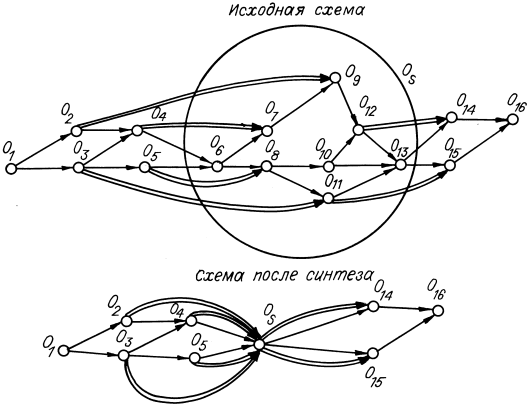
Let, for example,
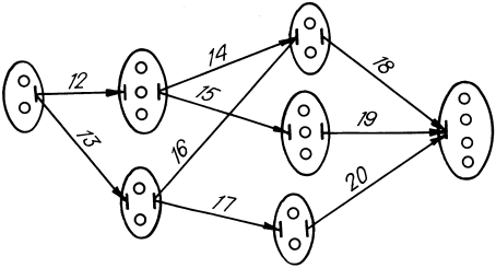
G(X,T,U) be the operator circuit shown below, without subcircuits with returns. Let us distinguish in the operator circuit
G(X,T,U) without subcircuits with returns the hammock-shaped subcircuits (
Figure 14):
Figure 14. Hammock-shaped subcircuits of the operator circuit.
We synthesize polysemantic polyinformation operators from hammock-shaped subschemes. We replace hammock-shaped subschemes with vertices, preserving all connections with subschemes.
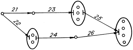
We obtain an operator scheme without hammock-shaped subschemes (
Figure 15):
Figure 15. Operator diagram without hammock-shaped subcircuits.
4.4. Splitting of Linear-cross Operator Schemes into Linear-like Ones
Theorem 5. A linear-cross operator scheme G(X,Y,U) can be split into an equivalent linear-like operator scheme G1(X1,Y1,U1).
Proof.
In a linear-cross operator scheme, we split the operators alternatively controlled by execution and the operators alternatively controlling execution into operators uniquely controlled by execution and uniquely controlling execution, preserving all information links and by execution with the corresponding operators.
We replace the operators alternatively controlled by execution with equivalent operators uniquely controlled by execution, and the operators alternatively controlling execution with equivalent operators uniquely controlling execution.
We obtain linear G(Xj,Y,U) subschemes that are not connected with each other either by information or by execution. Linear subcircuits G(Xj,Y,U) form a linear-shaped circuit equivalent to the original linear-cross circuit G(X,Y,U).
Which is what was to be proved.
4.5. Construction of Programs with Deterministically Connected Modules.
Definition 29. A subcircuit of an operator circuit that processes a group of input data independently of an additional subcircuit is called autonomous in input data.
Theorem 6. Any operator circuit defined in one algorithmic basis can be transformed by synthesis and splitting into an equivalent one defined in another algorithmic basis and consisting of subcircuits autonomous in input data.
Proof.
Any operator circuit can be transformed into a linear-shaped one. A linear-shaped circuit consists of subcircuits autonomous in input data.
Which is to be proved.
Theorem 7. Any program can be transformed into an equivalent program with deterministically connected modules.
Proof.
Let P be the original program. We transform the program P into an equivalent program with a linearly shaped operator scheme. The resulting program has operator subschemes that are autonomous with respect to the input data. We divide the resulting program into modules. We obtain a module-canonically connected program. The resulting program will be equivalent to the original program.
Which was required to be proved.
In the proposed formalism of operator schemes with natural interpretation, the solvability of the problem of constructing programs with deterministically connected modules is proven.
Examples of constructing programs with deterministic coupled modules for neurocomplexation are considered in published works
| [1] | Alexander Kirichenko. Neural Network Programming. Neurocomputing Toolkit. Created in the Intelligent Publishing System Ridero. 2020. |
| [2] | Zhengqing Liu, Musa Unal, Matthew J. Parkinson, Marios Kogias. DORADD: Deterministic Parallel Execution in the Era of Microsecond-Scale Computing. ACM. 2025. Vivekkothari. Difference between Deterministic and Nondeterministic Algorithms. 2022. |
[1, 2]
Programs with deterministic coupled modules can be obtained from programs with non-deterministic coupled modules by constructing and transforming their operator schemes into linear-cross schemes at the stage of neurocode generation. For programs with operator subschemes with returns and with hammock-shaped subschemes at the stage of neurocode generation, polyinformation polysemantic operators are formed in the form of software implementation by ensembles of intelligent decision-making agents based on the proposed theoretical foundations.
The proposed approach made it possible to continuously process large programs with deterministic coupled modules on the virtual memory of the supercomputer interpreter with preemptive replacement of modules on the virtual memory
| [2] | Zhengqing Liu, Musa Unal, Matthew J. Parkinson, Marios Kogias. DORADD: Deterministic Parallel Execution in the Era of Microsecond-Scale Computing. ACM. 2025. Vivekkothari. Difference between Deterministic and Nondeterministic Algorithms. 2022. |
[2]
. The interpreter command system is oriented towards the implementation of programs with linear-cross schemes.